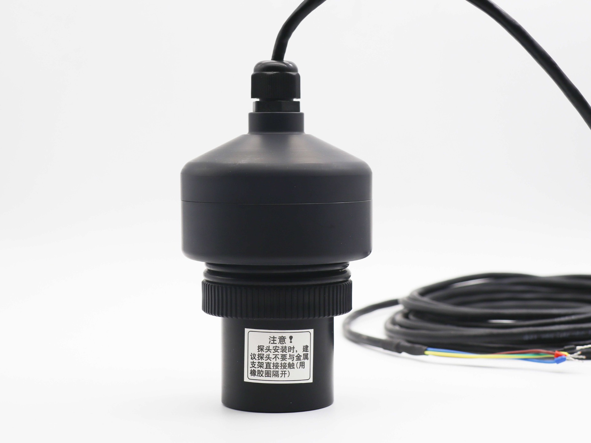

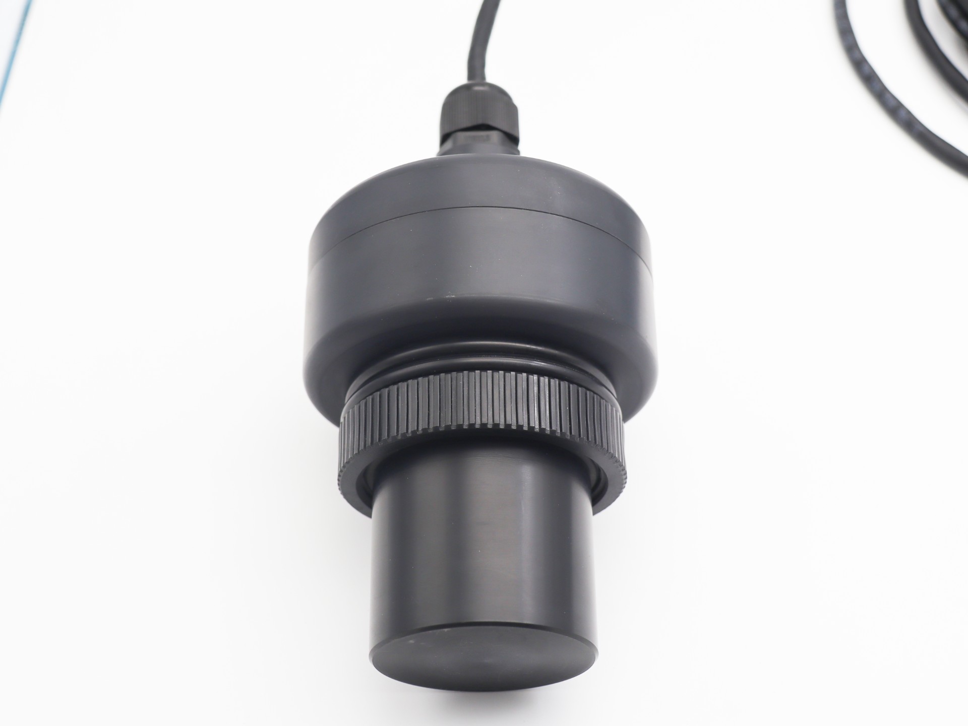
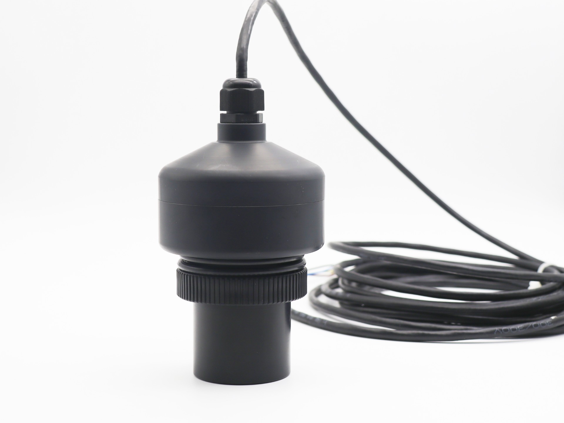
lHigh sensitivity
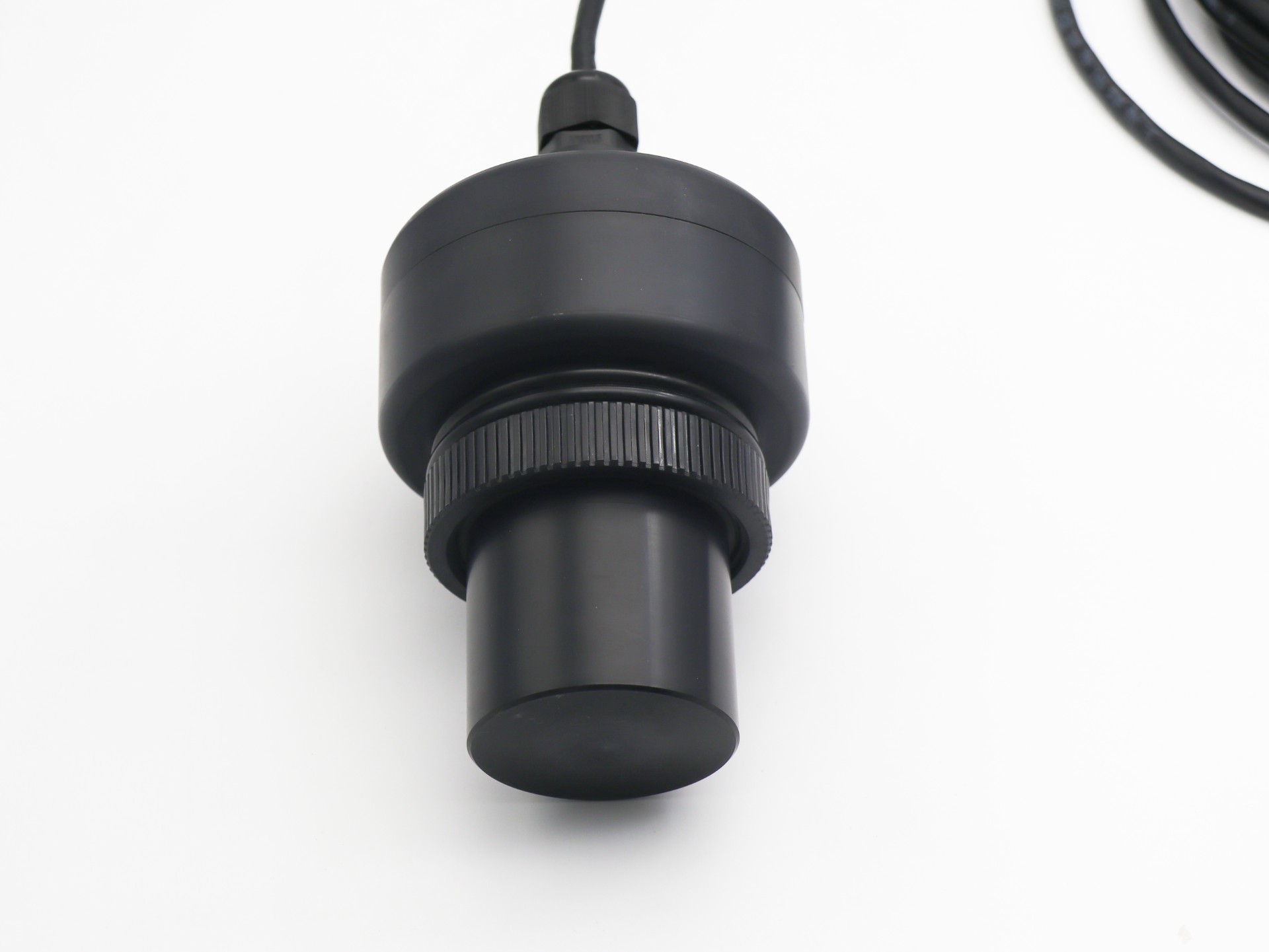
lFully sealed
lIP68 protection level
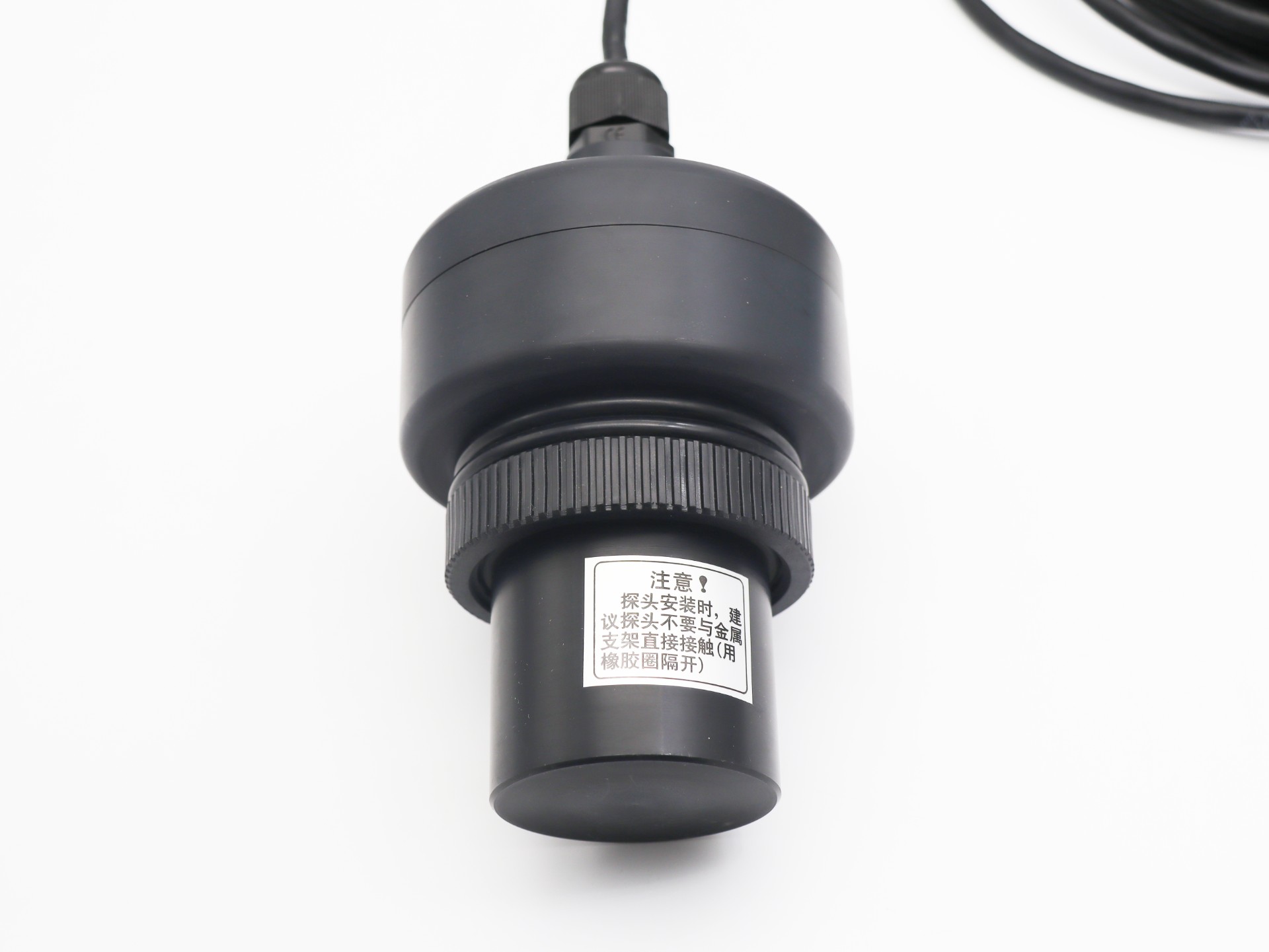
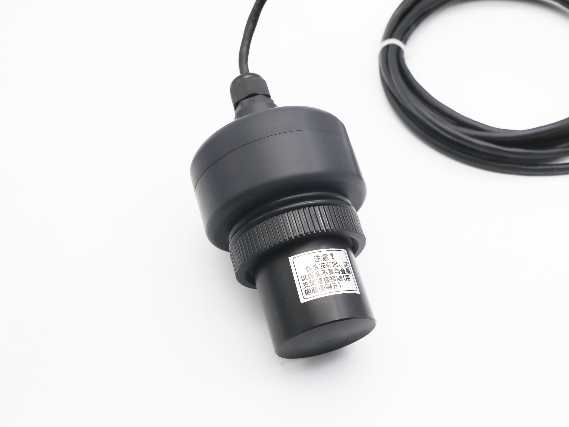
lCorrosion-resistant shell, suitable for corrosive media and applications

The unit is mm.
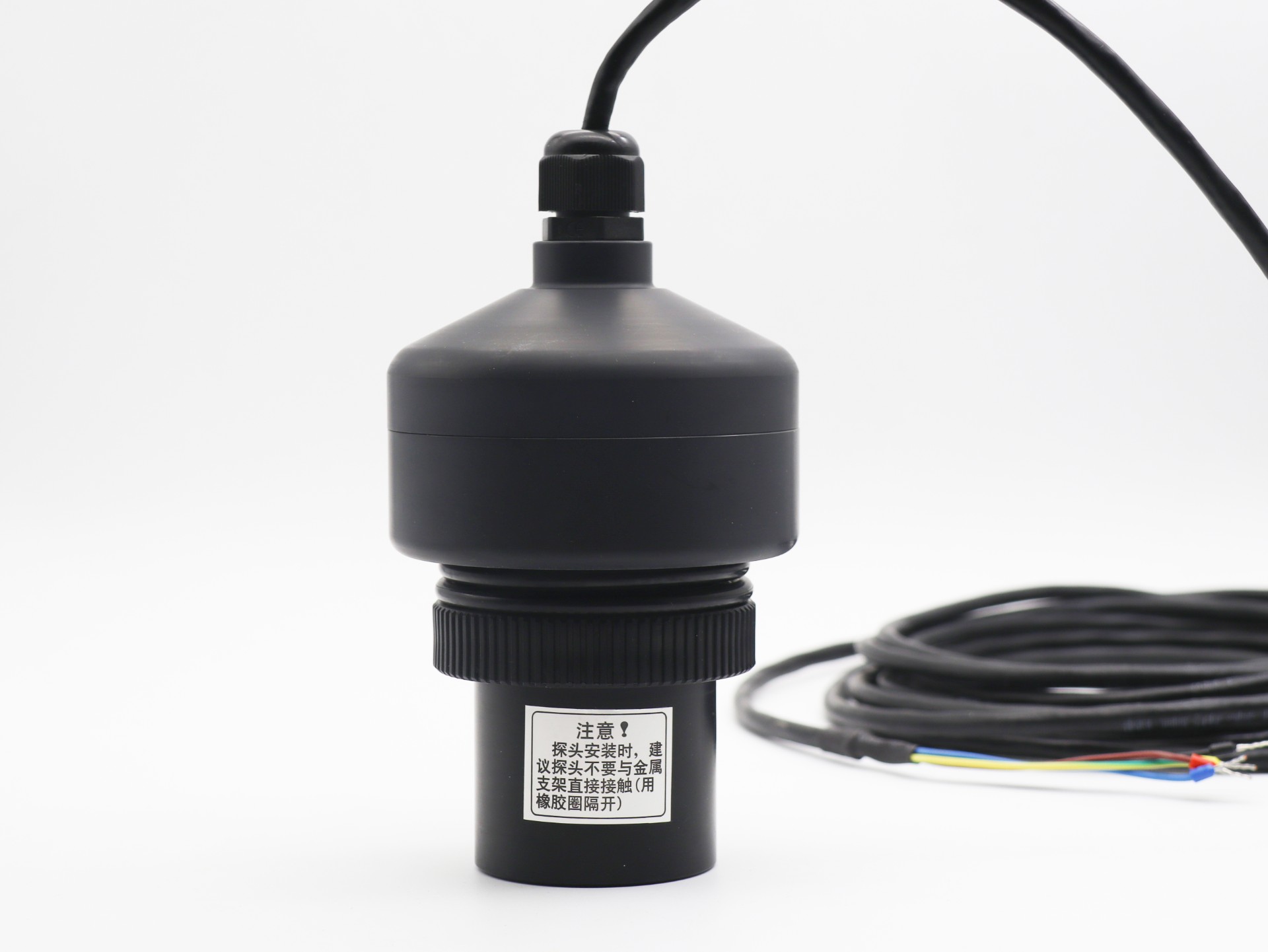
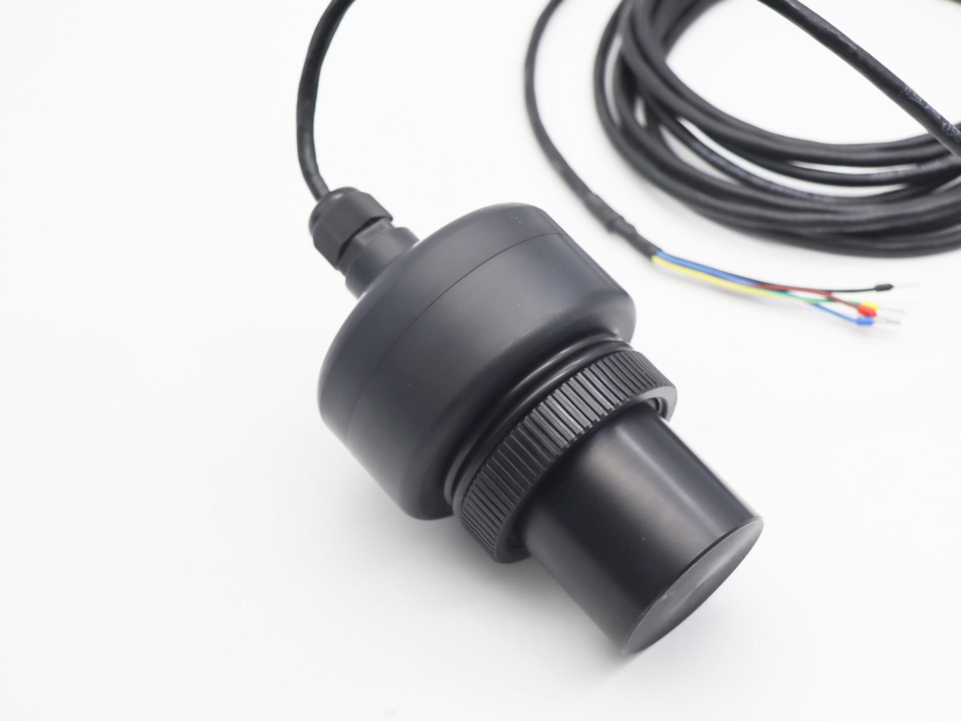
Line order | Color | Definition |
1 | red | Power is positive |
2 | black | Power return ground |
3 | yellow | Analog output, voltage output, current output switch output |
4 | blue | RS485 A+or uart TXD |
5 | green | RS485 B- or uart RXD |
Model:KUS620 | |
Measuring range | 600... 8000 mm |
Blind spot | 0 ... 600 mm(Within 600mm is an unstable working area, it is not recommended to work in this range) |
Supply voltage | 3.3 ... 12 V DC , Ripple 10 %SS |
Working current | ≤ 45 mA(Fastest measurement speed) Low power consumption version, sleep power consumption is less than 0.3mA, sending power consumption is 20mA (less than 2ms), receiving power consumption is not more than 5mA (less than 150ms) |
Output signal | 1 Programmable analog output 0-10V. 2 RS485 output. 3 Uart serial output 4 4-20mA output 5:Switch output |
Measurement accuracy | ≤1 % |
Temperature compensation | Yes |
Working conditions
Working temperature | -25…70℃(248...343K) |
Storage temperature | -40…85℃(233...358K) |
Other instructions
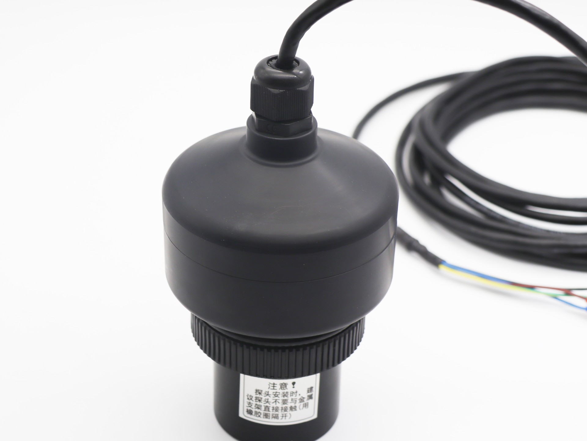
Electrical connection | 5-wire cable |
Protection level | IP68 |
Shell material | PVC /PVDF/PTFE(Default PVC) |
Analog
The analog output can be set via RS485, and the sensor can work in 8 modes. The specific reference is as follows:
Step 1: Connect to the host computer through the serial port debugging assistant or modus debugging assistant.
The second step is to set a near point reference distance point.
Step 3, set a far point reference point
The fourth step is to set the output voltage or current of the near-point reference point.
Step 5: Set the output voltage or current of the remote reference point.
The sixth step is to set the analog output as the switch characteristic selection.
The seventh step is to set the analog output as a linear output or switch output option.
Step 8, reset the sensor to make the new parameters take effect.
8 working modes of the sensor.
1: Open window mode by default
2: The window mode is closed by default
3: Single point mode is turned on by default
4: Single point mode is turned off by default
5: Single-point hysteresis mode is turned on by default
6: Single-point hysteresis mode is turned off by default
7: The presence or absence detection mode is turned on by default
8: The presence or absence detection mode is turned off by default
485 output data
485 output data is in MODBUS-RTU format. Refer to the software instruction manual for details.

KUS | Model | Output | Range | Describe |
|
| |||
Custom | ||||
0-10V | Analog 0-10V output | |||
0-5V | Analog 0-5V output | |||
0-3V | Analog 0-3.0V output | |||
4-20mA | Analog 4-20mA output | |||
SW | Switch output | |||
Uart | Uart serial port output MODBUS RTU protocol | |||
RS485 | RS485 output MODBUS RTU protocol | |||
XXX mm | XXX mm means the maximum measuring distance (Default 2500mm, 5000mm can be customized) | |||
KUS | 550 | RS485 | 2000mm | |